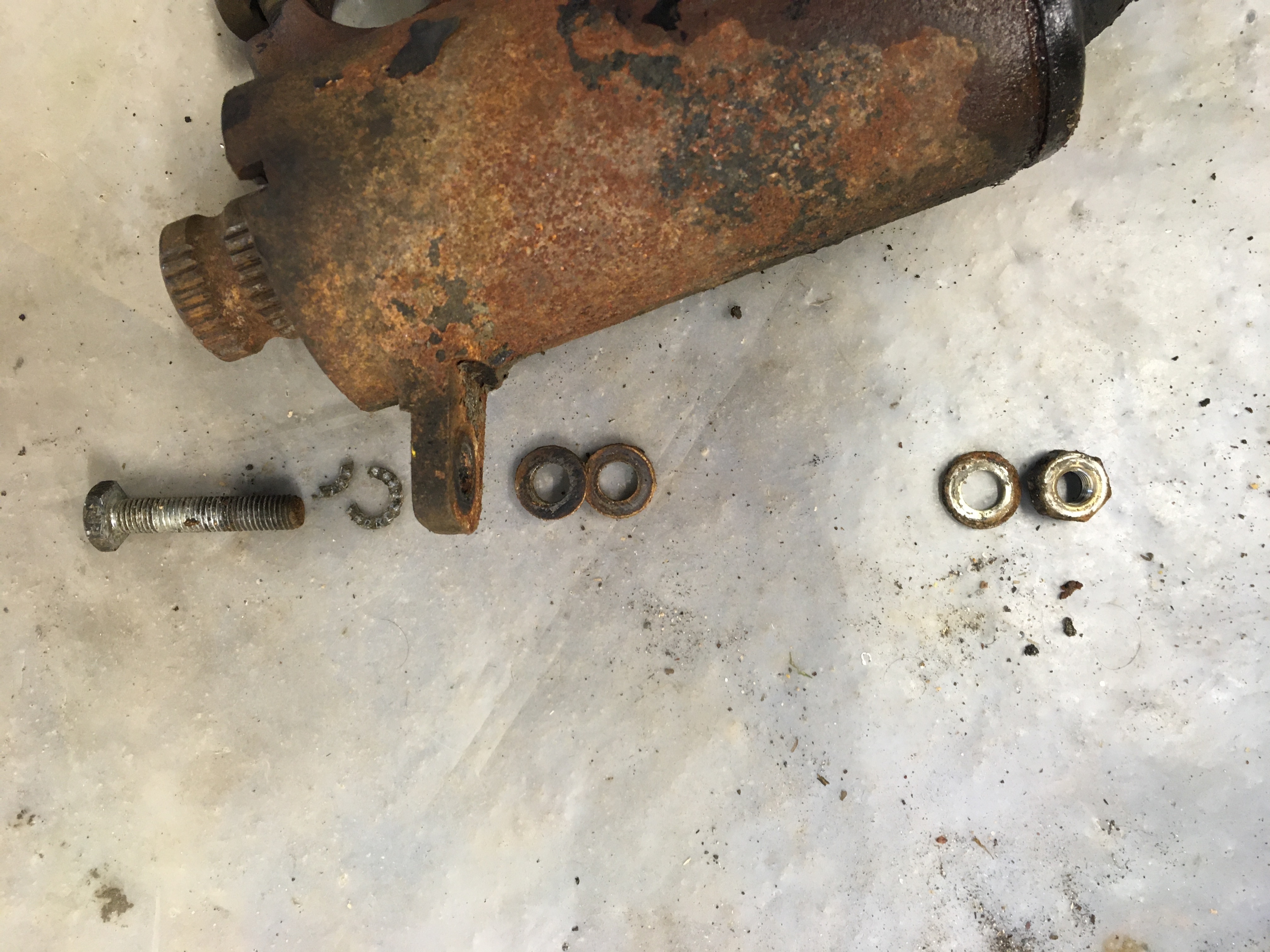
Because of the job they do, the bottom ends of the relays - down in the wheel arches - are quite exposed to rain and dirt. I'd started to remove and strip the relays back in May 2021. As well as being dirty and rusty, with the steering rack removed and the hubs linkages disconnected, I'd discovered that the relays were quite 'knotty' and didn't move smoothly.
The relays are held to the chassis by a large bolt passing horizontally through the chassis arm. The nuts on these are a real bugger to undo! Firstly they are on the wheel side of the chassis and so rust and seize on the bolt. Secondly the 'bolt head' ends are unconventional. In fact at first I didn't even realise they were bolt heads until someone explained what I was seeing to me.  |
Bolt head of the relay arm bolt
|
The bolts are hollow. Rather than being hex-headed, they have only two, shallow, flat edges. To complicated things further, the heads are recessed into deep washers or spacers - that's washers on the bolt end, not the nut end - meaning little of the heads remain exposed.
 |
Washer (or more accurately spacer) on the relay bolt
|
All in all it means that there is a risk of rounding the straight edges of the head when you try to undo the nuts. I soaked mine in penetrating oil occasionally before I tackled them and proceeded cautiously. In the end it was pretty straightforward to remove them.
The relays are able to pivot/ be rotated to some degree around this large central bolt, and so are fixed in position by smaller bolts that hold the heads down to the chassis arms. When I removed these smaller bolts I found a number of spacer washers.
 |
| The spacer washers are in the middle of the photo |
These are spacers that pack out the space between the lug on the side of the relay and the chassis.
 |
| Spacing washers under the relay mount |
It's all to do with the correct angle of the relay. When they are first fitted, a special tool is used to set the alignment of each steering relay.....
 |
Use of tool 1995-T too align the relay.
(photo credit unknown) |
The relay is rotated slightly until the pin engages in the dimple in the arm.......
 |
| Engaging the pin in the arm - more spacers needed! |
......and then a combination of different thickness spacers is used to pack out any gap.
 |
| That's better... |
I'm guessing all this is necessary because of slight differences in the construction of the chassis or differences in the machining of the relays - or maybe a bit of both. There could be a different number of spacers used on each relay - so keep them all, and don't muddle the relays up!
With the relays removed I set about dismantling. And things started to go wrong almost immediately. To stop it loosening, the edge of the threaded upper nut is peened over into a groove in the main body. I used a drift to bend that peened edge back in away from the relay body. I did that to both nuts.The upper nut needs a special tool to remove it. The tool needs to fit over the splined end of the arm and have four 'pins' that lock intro hole in the nut.
 |
Relay nut. Note the peened edge at the bottom
|
The tool can then be rotated to loosen the nut. That's the theory at least. I fashioned a crude tool out of an old socket with four pins welded around it's circumference and tried to use a ratchet to loosen the nut - but it wouldn't budge without using considerable force and several repairs to my home made tool. It was heavy going with the noise and feel of metal grinding on metal.
 |
Daylight outside, but truly in the 'heart of darkness' now.....
|
I soon realised what the problem was: the nut threads had been damaged by the peening (and my bashing?) and were out of alignment - squashed or misaligned in some other way. My efforts at removing the nut were probably damaging the threads on the body too. With the nut half in and half out, I had no option but to try and press on. The nut fought me every fraction of a rotation. I used heat. I used oil. I used brute force. My workbench looked like a battlefield. And this was only the first relay! Eventually the titanic battle was over and slowly but surely the nut was removed.

I tried to set my worries aside and I set about dismantling the relay. I was 'in the zone' and didn't bother to refer to the manual. With the nut removed, the arm had some freedom of movement in the body and the balls were dislodged from their bearing cups. With a bit of effort I was able to knock the arm out through the body. With it came some of the balls. The others remained glued inside the body with sticky, dirty grease.
With the top nut and relay arm removed, from the top end of the relay body I was able to winkle out the dished thrust washer, the top bearing cup and the top oil seal.
 |
| The top oil seal is beneath the bearing cup |
On the bottom, cranked arm, end of the relay is a protective metal dust cap. That was carefully levered off to reveal an oil seal. That was prised out and, beneath all the rusty grease, was a circlip......
 |
The circlip secures the bottom bearing cup
|
The circlip holds the bottom bearing cup in place. The arm bearing race - and so arm - is locked in position by that bearing cup but, with the circlip removed, the arm can be carefully tapped down and out. At this point I wished I'd referred to the manual!
All the grease and stray balls were scooped out of the body. The parts were cleaned and accounted-for before I examined them.
 |
| Relay arm dismantled |
Unfortunately several came up wanting.....On one relay, one of the bottom bearing cups was pitted in places.
 |
Pitted old bearing cup - and a new replacement
|
On the other relay, one of the ball channels in the arm itself was pitted.
 |
| Pitting damage to the bearing groove |
In both cases I think this was down to water penetration and rust. Before I pressed-on with a rebuild I needed to know whether these relays could be salvaged. I used a file to try and dress the damaged threads on the nut and the body but the nut was still reluctant to fit back on without cross-threading. Once again, Peter 'Badabec' Bremner came to the rescue. A friend of Peter's had put the correct thread on a large piece of metal and I was able to run that up and down the relay body, like a heavy-duty tap, to clean up the threads.
Peter had also made his own pin tool. Much better than mine.  |
Peter's pin tool came to the rescue
|
With the relay body threads cleaned up and using Peter's tool, I was then able to run the proper nut up and down the body. Now knowing that I could at least reassemble the relays, I set about cleaning, painting and acquiring replacement parts.
By peening the edge over, the top nuts become damaged and really need to be replaced each time you rebuild. Peter had rebuilt his relays (more on that later) and bought the last two NOS nuts available on Earth. No, really. I think he got very lucky there. I'd not seen them on sale before, and I've not seen them on sale since. The DS parts suppliers sell refurbished units, so perhaps there is a source for replacement top nuts? Perhaps it's the kind of part Citrotech sell?
On the plus side, Peter didn't want the felt dust seals from the botton of his new nuts and very kindly gave them to me. I left them to soak on LHM before fitting them - to give them a water resistant finish.
 |
| New felt dust seals |
 |
| The felt seals fit on the underside of the nuts |
I was able to find a pair of lower bearing cups for sale (these are slightly different to the upper bearing cups), and also sourced some new replacement ball bearings.
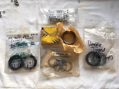 |
| Replacement parts |
These balls are 7.144mm in diameter (9/32") and widely available. Each relay has two oil seals inside. And they're different. The top seal is "double-lipped". As the name implies, it has a second lip that contacts the shaft within. This is to help provide an additional seal. I think, with some hunting, I could have sourced the seals from an oil seal supplier but, for convenience, I bought some from Der Franzose. Initially they sent me the wrong ones (more on that later too!), but I had no problems with an exchange.
So the top of the relays has a felt dust seal AND a double lipped oil seal. But even that combination didn't seem to stop water and mositure getting inside the relays.
At this point I was losing interest in the relays - or maybe gaining interest in the next jobs - the suspension arms. That would turn out to be another headache. You can read about that HERE.
I painted the relay parts when I painted the suspension arms last summer - more than a year after I'd removed and dismantled them - but then shoved them in a box again for six months while I got on with other things.
 |
| Painted parts |
This year, with the car now coming together, I couldn't delay rebuilding the relays any longer and so recently dug all the parts out. I remembered disassembly being a bit of a puzzle (especially as I didn't follow the correct procedure), but re-assembly was very straightforward and it (and I) went by the book. Manual 518 to be precise.
 |
All ready to go
|
Preparation
In
my case, and having had so much trouble with that top nut, I wanted
some options here. Before re-assembly I drilled and tapped a small hole
in the top edge of the body - in line with where the nut would be. I planned to fit grub screws. The hole needs to be up near the edge of the casting - with a risk it cracks. The hole and screw size need to be big enough to provide some 'bite', but not so big that the hole gets too close to the edge of the casting.
 |
| I added a hole to fit a grub screw |
 |
Tapping the hole for the grub screw
|
|
With the bearing cups in mind, before
you can fully reassemble the arm, it's advisable to make a simple tool
to help with the bottom cup....This is shown in Operation Dx. 433-3. |
 |
| Tool 3904-T |
This
tool is used to push home the arm assembly - and most importantly the
bottom bearing cup. I couldn't find any metal tube of quite
the right dimension. It needs to sit just inside the inner diameter of
the bodyso that it can press down on the face of the bearing cup. In the
end I found a tatty piece of domestic plumbing waste pie that was about
the right size. The cut out section slips over the cranked section of the arm.
 |
| My home made tool. |
I applied a little grease to the inside face of the body to help with the refitting of parts. The bearing cups will be a very 'snug' fit. Before I began in earnest, I did a trial fit of the two metal bearing cups in the body - to make sure that when it came to the crunch, they were going to fit nicely. This was especially important for me as I had bought replacement cups. You don't want to end up forcing and jamming them.
With the holes tapped and a tool made, and with the fit of the cups tested, I was all set to go.
 |
Relay arm parts
|
There was just one last thing. I familiarised myself with the job ahead and how all the parts should fit together. The scanned pdf diagrams available are quite blurry and don't show you what is inside very well. Here is a better quality scan of the relay arm parts.
 |
| Relay arm parts and their orientation |
In particular, it's worth noting the angles of the lips on the two seals (parts 5 and 8) and the orientation of the dished washer (part 2)
Top Bearing and Seal
The first step of reassembly was to fit the top oil seal in the body. This was pushed down to about the bottom of the machined area - about five or is inches down. Push it any further and it will simply fall inside the cast body. Look carefully at the lip as it's important to get the seal the right way round. The lip needs to to face up - towards the top of the relay.
 |
| New top oil seal in the relay body. Note the angle of the lip |
Next the top bearing cup and it's balls were fitted. The top and bottom bearing cups look similar, but the top cup is the one with the smaller diameter inner hole. Two points. Firstly, you need to hold all the 14 balls in place on the cup with a generous amount of bearing grease for fitting.
 |
| Top bearing cup - ready to fit |
Secondly, invert the body and fit the cup that way - it stops any balls falling into the body. Press the cup and ball assembly down (up) into the body until its resting against the oil seal.
 |
| Oil seal, balls, and bearing cup |
On top of the bearing cup, I placed the flexible (dished) washer. This needs to be fitted so that it's narrower end faces DOWN. If you fit it the other way up, it simply presses against the felt dust seal of the top nut and doesn't do it's job properly.
Next, the top nut was fitted. This should be fitted so that it's face is just below the top edge of the body (about 1mm or 2mm). If your oil seal was not pressed in far enough before, so the stack of seal, bearings and nut is above the rim - don't worry. The seal will yield under the nut and move down to the appropriate level. If you pressed the oil seal in too far, again - don't worry. Just fit the nut to below the edge of the body. Then, from the other end, gently push the seal back so that it contacts the balls.
The next job was to set up the relay arm for fitting. I polished up the bearing surfaces to try to compensate for some of the wear.
 |
I polished the bearing surface on a wheel
|
Relay Arm Assembly
The diameter of the ball joint eye is greater than the dimension of the arm shaft, so these parts cannot be fitted after assembly. I first slipped the metal sealing cap over the shaft. Make sure you get it the right way round. Next was the bottom oil seal. Again - make sure it's the right way round: the lip of the bearing needs to be facing towards the splined end of the relay arm. Next I fitted the lower bearing cup. The dished face, that carries the balls, need to face towards the splined end of the arm. The metal cup and oil seal were slid out of the way towards the ball joint eye. I positioned the bearing cup at it's approximate position with the corresponding groove in the relay arm
On the relay body, and with the relay body upside down, check that the balls of the top joint (the ones fitted first) are still in place. Some of the balls may have fallen inwards - blocking the hole in the seal - but they can be gently coaxed back into position with a screwdriver blade or similar.
Now take the arm assembly and generously coat the ball groove, and thinner part of the shaft at the splined end, with grease. Do the next step over a bench or similar so that you can check no balls get pushed out during assembly.
Hold the cup on the arm over the balls in the groove to stop them falling out. Gently, and gradually, push the splined end of the arm down through the body. Do not go too far or the bearing cup on the arm will simply get pushed back out - with the risk the balls fall out. Carefully locate the bearing cup in the body.
 |
| Fitting the bottom bearing cup |
So,
as the splined end starts to emerge from the other end of the body, pay attention to the
cup and balls on the relay arm. This is where you need to make sure the
bearing cup fits straight into the body and does not get snagged. You
want the arm to go through the body only at the pace that allows you to
keep the cup on the arm, in contact with the balls on the arm. They both
need to go back in together and this is where that tool gets used.
Placing the tool over the cranked arm, gently tap down on the tool, so that it presses on the cup. The cup will press against the bearings in the arm and gradually push the who lot through the body.
 |
Home made tool for fitting the bottom bearing
|
To make sure you are applying pressure evenly on the bearing cup, you can carefully rotate the arm a little and then tap again. In fact it helps to rotate the arm anyway, just to make sure nothing is binding anywhere.
Eventually you will find that the arm is pushed fully home (i.e. the dished shoulder of the arm is pressed against the top bearings - which are held in place by the top cup and top nut). How will you know? Well, if the assembly has gone in as it should, you will be able to see and groove for the circlip at the cranked end of the arm.
And the next step is to fit that circlip. I managed to snap one and promptly stick it through my finger. Now I know what having your ears pierced feels like.
Luckily they are a standard size and it was easy to replace. (The circlip - not the finger). If you find that not quite enough groove is exposed to fit the circlip, try backing the top nut off very slightly and then tapping the arm home again from the cranked end. With the circlip fitted, the oil seal can be pushed home and the metal sealing cap fitted.
It probably took more time for me to type the above, than it did to actually do the job. It just needed a bit of thought and preparation beforehand.
There is a particular torque for the top nut - but it's difficult to achieve without some kind of a nut tool that accepts a torque wrench. It's not very technical anyway: The nut is tightened to 6m.kg. I think this pushes everything together and removes any slack). The nut is then backed off until it is only just touching the dished washer. Finally the nut is re-tightened a third of a turn. this is expected to correspond to 2m.kg. However this assumes you are using a new dished washer and a new top nut.
Once you are happy, peen the edge of the nut over into the groove of the body. Or tighten your grub screw if you do as I did.
 |
| Grub screw in place |
From what I can gather, the arm should be held 'securely' in the body: with the relay unit held on it side, the cranked end of the arm should not fall under gravity if the unit is shaken slightly - yet should move smoothly (more smoothly than it did perhaps?) when you push it with your finger. You might need to tighten or slacken the top nut slightly until you are happy with the pressure.
My uncertainty over this is one of the reasons I chose to try using grub screws to secure the nut. A grub screw is probably not as secure as peening the nut edge over - but neither is it as destructive and I think that, if I needed to, the relay unit nut could be removed or re-adjusted again.
Alternatives
There are several alternatives to your own rebuild. If you're worried about your skills, or the quality and longevity, you can go for an upgrade. The arm is machined and re-profiled to take (three?) modern, sealed roller bearings. These kits can be bought for about £80 each - so temptingly cheap really.
 |
| Upgraded relay arm kit. Note re-profiling. (photo credit: Der Franzose) |
However there is another hurdle to be overcome before these can be used. As originally produced, the relay bodies are machined internally to accept bearing cups with a diameter of 46mm. It's the same for the oil seals. The new modern bearings have an outer diameter of 47mm. So before these arms can be used, you need to get the bodies machined to 47mm to suit. There was an error on Franzoses website and when I originally ordered replacement 46mm seals for my arms, 47mm seals turned up. Franzose gave me a no-quibble replacement, so I can't complain.
This cheaper route also relies on you being able to re-use your top nut and not buggering up the threads. Having already tried the rebuild route that I followed, Peter eventually went down the path of re-profiled arms and new seals. he was lucky enough to find new top nuts. That's why he was able to offload various bits on me. He knows his way around a lathe but had to seek out someone else to machine his bodies for him.
If all of this sounds like too much hassle, it looks as though you can buy these upgraded arms with all the work done for about £200 each. You need to send back your old arms to have them overhauled for the next customer.
 |
A re-profiled, and rebuilt arm (photo credit: Citrotech)
|
I probably spent about £70 in total rebuilding my arms. But there was effort, anxiety (and blood) along the way. What I've ended up with is better than what I had before, but almost certainly not as good as these rebuilt units. However it has left me free to waste my money on other things-DS.
My two arms have distinct casting marks and I will make sure I put them back on the sides they came from. I'll also make sure I put back all the relevant packing washers.