Another alternator rebuild!
 |
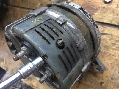
| Ducellier 7530A all cleaned up |
I know - I've already rebuilt the Ducellier 7558B alternator that was fitted to my car when I bought it (in fact I rebuilt it twice!). I covered that in my 2 June 2017 post. However that alternator was actually original equipment on a 73/74 car and I was always on the look out for a Ducellier 7530A for a 1968 car. Why not? The 7530A was the first Ducellier alternator fitted to Ds after Citroen made the switch from generators in late 1967 and they continued in use until 1970. There was also a Paris-Rhone equivalent.
Late in 2018, the very helpful Paul at Pallas Autos had remembered my 2014 search for a distributor and contacted me about a a distributor they had: it turned out that was a DV010, so not what I'd been looking for but, as part of the conversation, he generously offered me some unwanted parts - including a 6182A starter. More recently he turned up a Ducellier 'DX05' distributor (see my post of 15 August 2019) which I bought from him and he threw-in a Ducellier 7530A alternator that had turned up. I picked them up at the D rally last month.
 |
| As gratefully received |
Many perfectly good older alternators are removed from cars. It's quite common when a car has a voltage regulator problem, to replace the alternator for a newer one that has the voltage regulator built in to it. It's a cure for a DS and makes a lot of sense. Paul told me this particular alternator had only been removed from the car because it was to be replaced with modern one as part of a restoration. Someone had painted 'OK' on the side of the alternator at some point - so I was optimistic it was in working order. Mind you, they'd also written 'BEARS' on it as well, so perhaps it was worth getting checked out......
I had the alternator tested by my local auto-electrician. they really need to be tested under running conditions. They fit them up to a jig and run them from the pulley. I was told that (without the benefit of a regulator attached to limit voltage) this alternator was pushing out 16 volts at increasing revs - at which point the tester pronounced it had passed and wound it down again.
With that sorted, I began stripping it. As a design, the 75xx series of alternators were used on several different Ds over the years, however (and although the working principles are the same) the layout and construction of the earlier 7530A is a little different from the 7558, and even the 7530B that was used between them. In fact the 7530B is more like a 7551 and 7558 than it is a 7530A. The casing and layout of the 7530B is the same as the 7551 and 7558 (rather than the 7530A), however the 7530B has a shorter rotor shaft, "in-y" pulley nut and larger pulley - like the 7530A,. In contrast, the 7558 which has a longer shaft, "out-y" nut on a longer shaft and smaller diameter pulley. The point here being that not many bits are interchangeable......
 |
| Bottom: 7530A, middle: 7530B, top: 7558B |
The mounting bracket was removed. I planned to zinc-plate that. The pulley nut was removed by gripping the pulley in a vice. alternators are heavy and i didn't want it to slip out of the vice, so wedged my knee against it.
 |
| Gripping the pulley to remove the nut |
I made a careful note of the order of the washers and was careful not to lose the half-moon key.
 |
| Key, fan, shims, pulley and nut..... |
The cooling fan behind the pulley was made of plastic - another difference from the 7558. At least it meant one fewer parts to zinc plate.
The brush holder cassette was removed via the two screws at the back. Not the one on the top......If you undo that one before the complete holder is removed, a tiny nut behind it drops inside the alternator, potentially jamming the rotor. Don't ask me how I know.......
 |
| The two end screws hold the brush carrier in place |
 |
The third screw just holds one of the brushes in place
and has a nut hidden behind it. |
The location and cover arrangement for the rectifier is different from the later 7530B and 7558B alternators.
 |
| Removing the rectifier cover |
 |
| Using a socket to push out the bearing |
 |
| Works like a charm |
There was a dust shield ring on the casing side of the bearing.
 |
| Dust shield washer |
Unlike the 7558B, the bearing also seemed to be held in place by a rubber 'o' ring in a groove. I don't think it's meant to be water-tight. I don't think it has any purpose other than to gently hold the bearing in place? The bearings were filthy but otherwise okay. Rather than look to replace, I simply re-packed the grease.
 |
| Filthy bearing...... |
In the case of the bearing not on the shaft, I doused it in isopropanol alcohol to remove all the old grease and dirt.
 |
| ........clean bearing |
I pressed a paper-towel 'bib' over the rotor shaft and slotted the bearing back on as a stand. I gently heated some light grease it a metal pot. and similarly warmed the bearing to aid flow. (I had to be careful as one side of the bearing had a plastic seal and didn't want to melt that.) I poured the melted oil into the bearing and gave it a gentle spin to encourage the grease to penetrate. I warmed the bearing again to facilitate. I poured on more melted grease and repeated the process until the bearing was saturated/ full.
 |
| Re-packing a bearing |
I did something similar with the other bearing, but as it was stuck firmly on the shaft I just cleaned it out with a rag before 'topping it up'.
 |
| Re-greasing the rear bearing |
The pulley and pulley bolt were cleaned and repainted black. The pulley is a different diameter to that of the later 7558 alternator.
 |
| Pulley repainted. Note the keyway slot |
All the other bolts were cleaned and the plastic parts soaked and scrubbed.
I planned to have the body vapour blasted to clean it and was keen to preserve the little "Ducellier" identity plate. It wouldn't survive a blasting and I didn't want to bend and/ or break it by levering it off. I was thinking about drilling it out from the inside, when I I found two tiny holes already inside the case - through which I was able to push out the minute rivets that held it in place.
A little research confirmed that the correct replacement brushes are a "UX 67-68" set. The usual parts suppliers didn't seem to readily list these and I ordered a set from Ebay France.......
 |
| 1968 DS21 and 7530 - those will do! |
.......and ordered up a couple of long replacement bolts to go through the rectifier. Then I went on holiday - back to the very same place where my adventure had begun back in summer 2014.....
Back from holiday I picked up the vapour-blasted casing and, with the post delivered, I was just about ready to go.
 |
| All ready to go |
With everything cleaned and prep-ed, it went back together quickly.
After first seating the dust seal, I refitted the bearing to the nose of the front casing half.
 |
| Dust seal back in place....... |
There is usually a hiccup along the way. In this case I found that the three small ‘M4’ sized bolts that secure the plate over the bearing were reluctant to begin screwing home into the casing. I could have applied a bit of brute force but, with the casing being alloy, I risked stripping the threads. I’d experienced something similar before – when bolting the engine, bell housing and gearbox together. Having had the alloy parts vapour blasted, minute particles of media remained in the tapped threads – getting in the way of the bolts.
As then, the solution was to use a tap to gently clean out the thread. The important things to remember were (1) to use the right size of tap – I ran a nut over the M4 bolt, then over the tap to make sure it was the same size as I needed and (2) to not to force things and end up cutting a new and different thread!
 |
| Nose bearing secured behind plate...... |
I mounted the reassembled rectifier in the rear half of the casing.
 |
| Rectifier mounted..... |
I aligned the stator ring to the casing, firstly such that the long bolts would pass through both casing halves and the stator, and secondly ensuring that the wires from the rotor aligned with the rectifier terminals.
 |
Aligning bolt holes on the stator and casing.
Stator not quite seated |
I put a modest bed of grease in the recess for the end bearing and fitted the bearing and rotor shaft through the stator, pushing it home. I bedded the stator in it’s groove as far as it would go and then slipped the front casing half, with it’s bearing, over the rotor shaft.
 |
| ......Before |
It was starting to look like an alternator again now!
The alternator mounting bracket was refitted. While I'm on the subject, a couple of my alternators (the earlier ones: this 7530A and the 7530B) have got a little strut welded onto the side of the bracket.
 |
| Strut welded on the bracket |
When the alternator is fitted, this has the effect of limiting the upright fitting angle of the alternator.
 |
| The 'limiter' rests neatly against a 'step' on the block |
What it also means, of course, is that it defines the minimum length of drive belts that can be used. Perhaps that's no bad thing, but I am finding the 1162mm belts a bit of a tight squeeze given these 'limiters'. I bought some (very slightly longer) 1175mm belts but these were actually still supplied as 1162mm belts.
Moving on........I used some graphite powder to lubricate the inner channels of the brush holder and then fitted the new brushes I’d bought from France - checking that the brushes moved smoothly in their channels.
 |
| Fitting the new brushes |
When fitted, the brushes contact the two tracks of the slip ring on the rotor.
 |
| Just visible: slip ring on the rotor |
And when it was fitted, it looked like this:
 |
| Before....... |
 |
| ......after |
The key for the pulley shaft was greased a little to hold it in it’s groove and the plastic cooling fan and various shim washers were refitted, followed by the pulley.
Being careful not to crush the plastic cooling fan, I gripped the pulley in a vice (again supporting the weight of the alternator with my knee) and tightened the nut on the pulley shaft. This inevitably marked the paint on the pulley and I’d always planned to do a touch up on completion.
 |
| Pulley nut fitted..... |
The makers name plate was refitted. I didn’t want to risk the tiny rivets being too loose in their holes so mixed up a little Araldite and used a cocktail stick to introduce a small amount to the rivet holes. With the plate in place, the rivets were tapped home.
 |
| The makers plate is a nice period detail |
That was it. At the moment I have removed the 7558B from the engine so that I can have better access to fit the radiator and especially that tricky bottom radiator-to-pump hoses. When it's time for re-assembly, I'll drop this 7530A on instead. In the meantime it's gone back in a box.


