Wednesday, 21 August 2019

Ducellier 7530A Alternator - Strip Down and Overhaul

Another alternator rebuild!
Ducellier 7530A all cleaned up
I know - I've already rebuilt the Ducellier 7558B alternator that was fitted to my car when I bought it (in fact I rebuilt it twice!). I covered that in my 2 June 2017 post. However that alternator was actually original equipment on a 73/74 car and I was always on the look out for a Ducellier 7530A for a 1968 car. Why not? The 7530A was the first Ducellier alternator fitted to Ds after Citroen made the switch from generators in late 1967 and they continued in use until 1970. There was also a Paris-Rhone equivalent.

Late in 2018, the very helpful Paul at Pallas Autos had remembered my 2014 search for a distributor and contacted me about a a distributor they had: it turned out that was a DV010, so not what I'd been looking for but, as part of the conversation, he generously offered me some unwanted parts - including a 6182A starter. More recently he turned up a Ducellier 'DX05' distributor (see my post of 15 August 2019) which I bought from him and he threw-in a Ducellier 7530A alternator that had turned up. I picked them up at the D rally last month. 
As gratefully received
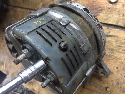
Many perfectly good older alternators are removed from cars. It's quite common when a car has a voltage regulator problem, to replace the alternator for a newer one that has the voltage regulator built in to it. It's a cure for a DS and makes a lot of sense. Paul told me this particular alternator had only been removed from the car because it was to be replaced with modern one as part of a restoration. Someone had painted 'OK' on the side of the alternator at some point - so I was optimistic it was in working order. Mind you, they'd also written 'BEARS' on it as well, so perhaps it was worth getting checked out......

I had the alternator tested by my local auto-electrician. they really need to be tested under running conditions. They fit them up to a jig and run them from the pulley. I was told that (without the benefit of a regulator attached to limit voltage) this alternator was pushing out 16 volts at increasing revs - at which point the tester pronounced it had passed and wound it down again.

With that sorted, I began stripping it. As a design, the 75xx series of alternators were used on several different Ds over the years, however (and although the working principles are the same) the layout and construction of the earlier 7530A is a little different from the 7558, and even the 7530B that was used between them. In fact the 7530B is more like a 7551 and 7558 than it is a 7530A. The casing and layout of the 7530B is the same as the 7551 and 7558 (rather than the 7530A), however the 7530B has a shorter rotor shaft, "in-y" pulley nut and larger pulley - like the 7530A,. In contrast, the 7558 which has a longer shaft, "out-y" nut on a longer shaft and smaller diameter pulley. The point here being that not many bits are interchangeable......
Bottom: 7530A, middle: 7530B, top: 7558B
The mounting bracket was removed. I planned to zinc-plate that. The pulley nut was removed by gripping the pulley in a vice. alternators are heavy and i didn't want it to slip out of the vice, so wedged my knee against it. 
Gripping the pulley to remove the nut
I made a careful note of the order of the washers and was careful not to lose the half-moon key. 
Key, fan, shims, pulley and nut.....
The cooling fan behind the pulley was made of plastic - another difference from the 7558. At least it meant one fewer parts to zinc plate.

The brush holder cassette was removed via the two screws at the back. Not the one on the top......If you undo that one before the complete holder is removed, a tiny nut behind it drops inside the alternator, potentially jamming the rotor. Don't ask me how I know.......
The two end screws hold the brush carrier in place


The third screw just holds one of the brushes in place
 and has a nut hidden behind it.
The location and cover arrangement for the rectifier is different from the later 7530B and 7558B alternators. 
Removing the rectifier cover
It was surprisingly mucky inside. Unlike the 7558B, the wires ended in ring terminals, so there was nothing to unsolder this time.
Stator and diode wires on the rectifier
I split the case and remove the stator coil and rotor.

I set about removing the rectifier. This is held to the body by the M6 and M5 terminal bolts.

I made a note of the arrangement of plastic insulating spacers and washers. The rectifier is completely different to that on the 7558B.

The main body was now in pieces.

I cleaned the loose rust off the stator and repainted it in the original lime green colour.

I examined then cleaned up the slip ring. It wasn't badly worn at all. 
Slip ring looked in good condition
Fitting this 7530 to my car meant I wouldn't have to worry about the excessive wear i'd found on my 7558B back in June 2017. The next photo is from a Paris-Rhone alternator. This is what 'worn' can look like!
Excessively worn slip ring.......
I stripped down the rectifier to clean it. This involved bending back the tabs of three locking plates on the screws used to hold the wire ring ends, so that they could be turned. 
Locking tab on the rectifier terminal bolt
The rectifier - split
The diodes have contact wires soldered directly to them and the diodes themselves are pressed into the rectifier body. The diodes didn't seem to want to budge and so I left them in situ - carefully cleaning around them instead. The wire sleeves were also colour-coded red and black. At least that meant I couldn't muddle them up when re-assembling.......
Diode wires colour-coded red
I replaced the two main terminal bolts and put it all back together. It looked a lot better.

When I took apart the main alternator body, the bearing at the tail end came out on the rotor shaft. It seemed to be on there quite firmly so I left it in place. The bearing at the nose end remained held in place behind a cover plate.

Using a socket of an appropriate size, I carefully tapped the bearing out from the outside-in.
Using a socket to push out the bearing
Works like a charm
There was a dust shield ring on the casing side of the bearing.
Dust shield washer
Unlike the 7558B, the bearing also seemed to be held in place by a rubber 'o' ring in a groove. I don't think it's meant to be water-tight. I don't think it has any purpose other than to gently hold the bearing in place? The bearings were filthy but otherwise okay. Rather than look to replace, I simply re-packed the grease.
Filthy bearing......
In the case of the bearing not on the shaft, I doused it in isopropanol alcohol to remove all the old grease and dirt.
........clean bearing
I pressed a paper-towel 'bib' over the rotor shaft and slotted the bearing back on as a stand. I  gently heated some light grease it a metal pot. and similarly warmed the bearing to aid flow. (I had to be careful as one side of the bearing had a plastic seal and  didn't want to melt that.) I poured the melted oil into the bearing and gave it a gentle spin to encourage the grease to penetrate. I warmed the bearing again to facilitate.  I poured on more melted grease and repeated the process until the bearing was saturated/ full.
Re-packing a bearing
I did something similar with the other bearing, but as it was stuck firmly on the shaft I just cleaned it out with a rag before 'topping it up'.
Re-greasing the rear bearing
The pulley and pulley bolt were cleaned and repainted black. The pulley is a different  diameter to that of the later 7558 alternator. 
Pulley repainted. Note the keyway slot
All the other bolts were cleaned and the plastic parts soaked and scrubbed.

I planned to have the body vapour blasted to clean it and was keen to preserve the little "Ducellier" identity plate. It wouldn't survive a blasting and I didn't want to bend and/ or break it by levering it off. I was thinking about drilling it out from the inside, when I I found two tiny holes already inside the case - through which I was able to push out the minute rivets that held it in place. 

A little research confirmed that the correct replacement brushes are a "UX 67-68" set. The usual parts suppliers didn't seem to readily list these and I ordered a set from Ebay France....... 
1968 DS21 and 7530 - those will do!

.......and ordered up a couple of long replacement bolts to go through the rectifier. Then I went on holiday - back to the very same place where my adventure had begun back in summer 2014.....

Back from holiday I picked up the vapour-blasted casing and, with the post delivered, I was just about ready to go.
All ready to go
With everything cleaned and prep-ed, it went back together quickly.


After first seating the dust seal, I refitted the bearing to the nose of the front casing half.
Dust seal back in place.......
There is usually a hiccup along the way. In this case I found that the three small ‘M4’ sized bolts that secure the plate over the bearing were reluctant to begin screwing home into the casing. I could have applied a bit of brute force but, with the casing being alloy, I risked stripping the threads. I’d experienced something similar before – when bolting the engine, bell housing and gearbox together. Having had the alloy parts vapour blasted, minute particles of media remained in the tapped threads – getting in the way of the bolts.

As then, the solution was to use a tap to gently clean out the thread. The important things to remember were (1) to use the right size of tap – I ran a nut over the M4 bolt, then over the tap to make sure it was the same size as I needed and (2) to not to force things and end up cutting a new and different thread!
Nose bearing secured behind plate......
I mounted the reassembled rectifier in the rear half of the casing.
Rectifier mounted.....
I aligned the stator ring to the casing, firstly such that the long bolts would pass through both casing halves and the stator, and secondly ensuring that the wires from the rotor aligned with the rectifier terminals.
Aligning bolt holes on the stator and casing.
Stator not quite seated
I put a modest bed of grease in the recess for the end bearing and fitted the bearing and rotor shaft through the stator, pushing it home. I bedded the stator in it’s groove as far as it would go and then slipped the front casing half, with it’s bearing, over the rotor shaft.

With a bit of fiddling I got the casing halves and green stator ring aligned and squeezed them together. If the stator ring is not squarely seated in the grooves of the two halves, it will be slightly out of alignment and the rotor will catch it as it rotates. 
Casing halves brought together.
Now the stator is seated!
With a bit of persuasion (ignore that hammer in the photo!) I got the parts aligned and seated, and slipped the long bolts through their holes. Tightening these also helped to ensure the parts sat ‘true’.

Casing bolted back together
I gave the shaft a spin to make sure it ran smoothly and without catching the rotor. Satisfied, I connected up the rotor-to-rectifier wires and refitted the dust cover over the rectifier. 
After......
......Before
It was starting to look like an alternator again now!

The alternator mounting bracket was refitted. While I'm on the subject, a couple of my alternators (the earlier ones: this 7530A and the 7530B) have got a little strut welded onto the side of the bracket.
Strut welded on the bracket
When the alternator is fitted, this has the effect of limiting the upright fitting angle of the alternator. 
The 'limiter' rests neatly against a 'step' on the block
What it also means, of course, is that it defines the minimum length of drive belts that can be used. Perhaps that's no bad thing, but I am finding the 1162mm belts a bit of a tight squeeze given these 'limiters'. I bought some (very slightly longer) 1175mm belts but these were actually still supplied as 1162mm belts.

Moving on........I used some graphite powder to lubricate the inner channels of the brush holder and then fitted the new brushes I’d bought from France - checking that the brushes moved smoothly in their channels. 
Fitting the new brushes
When fitted, the brushes contact the two tracks of the slip ring on the rotor.
Just visible: slip ring on the rotor
And when it was fitted, it looked like this:
Before.......
......after
The key for the pulley shaft was greased a little to hold it in it’s groove and the plastic cooling fan and various shim washers were refitted, followed by the pulley.

Being careful not to crush the plastic cooling fan, I gripped the pulley in a vice (again supporting the weight of the alternator with my knee) and tightened the nut on the pulley shaft. This inevitably marked the paint on the pulley and I’d always planned to do a touch up on completion.

Pulley nut fitted.....
The makers name plate was refitted. I didn’t want to risk the tiny rivets being too loose in their holes so mixed up a little Araldite and used a cocktail stick to introduce a small amount to the rivet holes. With the plate in place, the rivets were tapped home.
The makers plate is a nice period detail
That was it. At the moment I have removed the 7558B from the engine so that I can have better access to fit the radiator and especially that tricky bottom radiator-to-pump hoses. When it's time for re-assembly, I'll drop this 7530A on instead. In the meantime it's gone back in a box.

Thursday, 15 August 2019

Ducellier 4155 D distributor - Strip Down and Overhaul

I decided to rebuild the mechanical Ducellier 4155 distributor I had recently acquired from Paul at Pallas Autos. If someone has an ignition problem - or even a general running problem - a quick and easy response is to suggest they upgrade to "123 electronic ignition"  But that's an expensive solution and some people don't have the luxury of splashing out like that. Servicing their existing distributor might solve  - or eliminate a suspected problem.
Finished results
If you’ve read my post from 16 December 2018, you’ll have read that, when I started my restoration, I discovered that my car had the wrong distributor fitted..........

Both Ducellier and SEV-Marchal made and supplied distributors for Ds. The brand shouldn’t matter, however different models of D have different variants of distributor - and for a good reason. By virtue of an arrangement of weights and springs, they are set up to behave differently (have different advance curves/ characteristics) under engine load. For optimum engine performance it’s important to have the right one. Putting the clues together was like following the Da Vinci Code! 
DV = 'Wrong distributor not 'Da Vinci'......
Two separate tables in Operations D.210-00 and D.210-0 in Manual 814 list the appropriate distributor for each model of DS. My DX2 engine had been fitted with a Ducellier 4254D (coded DV-010A signifying it is for a DV engine). I couldn’t find a reference to a 4254D in the tables but a DV-010A was used on D Specials between 1969 and 1972 and then on DS23s (!?). 

Putting the clues together......
My 1968 DX engine should (apparently) have had either a Ducellier 4155B or a SEV-Marchal A147 distributor (both carrying the code “DX-05b” signifying they are for a DX engine). The tables also showed that, at a push, a Ducellier 4253B or SEV-Marchal A222 (both coded DX-05i and as fitted to DSuper 5s) could be used. As I say, the right SEV-Marchal distributor would do the same job, but as all the other equipment on my car was Ducellier brand, I was keen to find a 4155B. So I started hunting…….

During my online research “123 electronic Ignition” kept cropping up as an alternative to a conventional distributor. As it is electronic, via a small selector hidden behind a hex nut, 123 can be set up to replicate the different advance characteristics of different DS distributors - including the DX-05. Instructions with the 123 include a look-up table to tell you which indicator position corresponds to what DS engine and what DS advance curve - so those tables above are very handy to have.
123 can replicate different DS advance curves. 
123 is said to give more consistent firing and overall performance - in terms of starting and smooth, consistent running. However at about £275, 123 wasn’t cheap and I resolved to stick with a mechanical distributor - partly for originality, but mostly because of cost! I reasoned that with many DS owners making the switch to 123, and with so many DS21s and DSuper5s around, it shouldn’t be too hard to find an unwanted DX-05 distributor. Should it?

I contacted the range of DS parts suppliers that seemed to have cropped up while my car had been off the road - Pallas Auto, DS Workshop, Citroen Classics and Peacock Engineering  - but none of them could help. Pallas Auto had a good hard search for me and sourced a distributor marked “DX-05i” from a 2347cc DX4 engine - but confusingly that turned out to be a 4259B distributor so I let it pass - sure a DX-05b would turn up eventually. 

At about this time in 2014 I went to visit Toni Papa and his DS in London. We discussed 123. He’d fitted it and was very happy with it. Was his old distributor going begging by any chance? Sorry, no: he also carried his old mechanical distributor around in his boot as an emergency spare if the 123 failed (they rarely do you know....). Anyway, perhaps this was why I was having trouble finding an old DX-05b? At the time (and with an engine rebuild yet to happen), a distributor wasn’t a priority and I dropped the search.

By 2018 I was near to completing my engine rebuild. I had mellowed as well as aged and gave in: I bought 123 electronic ignition at Citromobile as it was too cheap to resist. I took comfort from the fact that it could at least be set up to correctly mimic a DX05b. So the deed was done.

However when it came to a first test start of my engine I actually re-fitted my old (wrong) DV-05 distributor! (You can read about that in my 16 December 2018 post). I am saving the fitting of the 123 until the engine is back in the car and I fit the new wiring loom. At that point I had planned to keep my DV-010 distributor in the boot as an emergency spare if the 123 ever failed. I’d still have preferred a DX-05 as a spare though……

In one of those weird twists, in June 2019 someone on one of the Facebook DS groups put out a plea for a distributor for a DSuper5. Paul at Pallas Auto offered a DX-05b! Luckily for me it turned out the searcher was actually after a DY010A distributor for either a D Special (or maybe a five geared D Special?). Anyway, the key point being that both of those are 1985cc engined cars. As such, the DX-05 was not wanted.

I contacted Paul. Yes - not only was it a Dx-05b, it was a Ducellier! And yes - it was still available. A deal was struck. I still planned to use the 123 distributor I had eventually bought but at last I now had an appropriate back up distributor to carry in the boot. I picked it up from Paul at the D rally in July. It is indeed marked DX-05b and so for a 1968 DX engined DS.
The elusive "DX-05b".........
But, oddly, the model number is 4155D (not 4155B). I couldn't find any reference to a 4155D distributor in the tables in the 814 Manual - but neither could I find evidence of a 4155B on the internet . Well not yet anyway. I'm concluding the manual has a typo and suspect they got muddled because of the 'b' of 'DX05'.

It looked as grubby and unloved as any other distributor you see. Although it's only for use as a back-up, I decided to strip and clean it.....

The procedure isn't covered in either volume of manual 814, but there are some pretty basic (and incomplete) instructions at Operation DX.211-3 in Manual 518 from 1966. Two procedures cover the Ducellier and then the SEV-Marchal distributors of the day and are at least helpful reference.

With the distributor cap removed and rotor arm off, the first job was to remove the square-headed 'primary terminal' screw from inside the body. 
Black wire from contact breakers is connected to the primary terminal
This primary terminal is insulated from the outer casing of the distributor by plastic spacers and has a surprising number of nuts and washers on it. These included the broken ring terminal end of a wire. I suspect this may have been an earthing lead? I'm not convinced all the others are needed.
Primary terminal screw - with insulators, washers and nuts
With the primary terminal out of the way, the carrying plate - suspended over the springs and weights and carrying the contact breakers - could be removed. This is held in place by three screws.......
The carrying plate is suspended within the distributor
......two of which also carry the black spring clips for the distributor cap. And in the case of one of those screws, also the condenser.
Screw secures carrying plate and also clip
Both parts of the contact breakers were removed, allowing access to the cam follower and spring.   (I haven't a clue what the cam follower does. It is spring loaded and slides in a track in the carrying plate. I just don't know why.) I gently held this back with a screwdriver blade to enable me to slip the carrying plate over the drive shaft.
Holding back the cam follower with a screwdriver tip
Lifting out the carrying plate then revealed the cam beneath, complete with weights and springs - the heart of the distributor.
Cam with weights and springs on the rotor.
Turning to the other end of the distributor, I prepared to remove the roll pin holding the drive head in place. 
The drive head
The drive head has a 'big half' and a 'small half' and engages in the drive socket inside the distributor drive tower. That, in turn, is driven by the rotation of the camshaft, which is driven by a chain from the crankshaft.

To maintain the correct relationship (firing order and point) between crankshaft rotation and the rotor on the top of the distributor, it's important that the drive head on the bottom of the distributor spindle..........
Drive head. Note "big half" at the bottom
........is correctly aligned to the notch on the top of the cam.....

.... as that then sets the position of the rotor arm itself.
Locating lug inside the rotor arm
Making a note of their relative positions, I drifted out the roll pin.
The drive head is held on the spindle by a roll pin
Cradling the upturned distributor over a vice I then drifted out the drive spindle to free the drive head - remembering to catch the assembly before it fell to the ground!
Freeing the drive head from the drive spindle
On the outside of the body was the drive head, together with two thin shim washers sandwiching a fibre  'celeron' washer. There was a similar three washer arrangement inside the body underneath the cam plate.
Spindle and washer arrangement
With the spindle freed from the distributor body I could now have a good look at the weight and spring arrangement. I was surprised to notice that the two springs were completely different sizes.
Weights and springs on the distributor cam
Some quick Googling revealed that his was nothing to be alarmed about and that it was quite acceptable to have springs of different sizes on the same cam. I'm guessing that using different combinations of springs is one of the main ways to give different models different behavioural characteristics. I unhooked the springs.
Note different sized springs
I removed the circlips that hold the weight guides in place on the cam and removed the screw on the tip of the spindle. This is meant to be covered with a felt pad which is kept soaked in oil. This lubricates the cam on the spindle (and possibly the spindle in the distributor body itself?). Both my distributors lack this felt pad but it won't be hard to make something up. I separated the cam from the drive spindle. The cam has the four eccentrics which, when the cam rotates, open and close the contact breakers.
To the left: drive spindle with weights. To the right: the cam
I removed the circlips that held the the weights to the drive spindle.
Weights and cams separated 
The many bits were then thoroughly cleaned and, while we were away on holiday, I had the body vapour blasted for good measure.

Under the rotor on the spindle was a recessed area that seemed to be packed with something other than dirt and with the consistency of clay. Was it graphite paste to reduce friction? Was in a disintegrated rubber seal?I didn't know so left (what was left of) it alone.
Black 'clay' under the rotor
I noticed that one of the spring posts seemed to be bent from the perpendicular. This would be putting the spring under more tension. I wasn't sure whether this was some kind of micro-adjustment from when the distributor was assembled and calibrated so left that alone too.
Spring post on the right seems bent?
Reassembly is the reverse of disassembly, but I will go through it anyway.

The weights were relocated on their pivots. 
Refitting a weight
Manual 518 says to 'lightly oil' parts on reassembly. By and large I took this advice - only using light grease at a couple of points.

The 'rollers' that locate the weights in the cam were refitted........

I used a little light grease on the outer circumference to aid smooth movement in the slots of the cam, and the cam was then duly refitted on the end of the lubricated spindle.
The cam was located overs the rollers of the weights
Circlips were replaced and the screw holding the cam to the spindle was tightened. I checked for free movement of the cam and excessive float.
The cam was screwed onto the drive spindle
This is perhaps a good point to give a basic explanation of how a mechanical distributor works. For each cylinder/ piston in the firing sequence, that ignition point is triggered by the rotation of the rotor arm in the distributor cap. The compressed fuel/ air mix in your engine takes time to combust and ignition needs to start and complete at an optimum point of the piston stroke to generate optimum power. As engine speed increases, the pistons are of course moving faster. Without the advance mechanism in the distributor, this would mean that the piston had passed it's optimum compression point by the time the fuel eventually combusted - leading to reduced power......

As you can see in the photo above, the rotor arm sits on a cam which is only indirectly connected to the rotor: the rotor has two weighted 'arms' fitted to it, which locate into curved slots in the cam. As the drive spindle and rotor rotate faster, the inertial force on the weights overcomes the countering centripetal force provided by the springs on the cam and the weights lever outwards rotating the cam with them - slightly.  The rotor arm perched on top is similarly rotated a little - meaning that the ignition is 'advanced' relative to the movement of the drive spindle, camshaft, crankshaft and of course pistons: ignition takes place a little sooner to give the fuel time to still combust at the optimum point of compression.

The springs are not connected, but here is a quick video demonstration of the movement of the weights and rotor arm:


VIDEO: demonstration of distributor advance

I'm guessing that different lengths of grooves in the cam would allow the rotor to rotates by differing numbers of degrees, and that different spring tensions would determine the engine revs at which the weights began to move. Is that how it works?

Anyway, back to the rebuild. The springs were added. There were a little tricky to locate. I put a little light grease on the underside of the rotor where the strange 'clay' packing was. With the three washer combo then in place and the spindle oiled, it was refitted in the distributor body.
Rotor assembly back in the distributor body
At the bottom end, the three washers were refitted and the drive head replaced with the roll pin. 

With the position of the cam on the rotor now set by the weights and springs, I was careful to orientate the drive head on the spindle to it's correct position relative to the slot in the rotor.

There was a little more float in the spindle than I was happy with and I should really have experimented with adding an extra shim washer to the sets of three - except I didn't have any big enough to go over the shaft. The drive head is easy to remove so it's something I can come back to.

On the carrying plate, the cam follower (what DOES that do??) was refitted in it's guide and against it's spring. I used a little light grease as it seemed to have been greased previously.
Refitting the cam follower......
The carrying plate was slipped over the end of the cam. It was easy to work out which way round it went as it will only be screwed in place at three points.
Carrying plate relocated. The round hole is for the 'primary terminal'.
I had a dig around and turned up a new Lucas condenser and new set of Bosch contact breakers. 

The breakers were refitted.
Fitting the moving contact breaker
The primary terminal and all the nuts and washers were next. The square-headed screw and first insulator go inside the shell of the distributor. 
The primary terminal
The round plastic washer and the rest go outside of the body. The contact breaker wire was fixed to the primary terminal.

The condenser and distributor cap clips were refitted - in the process serving to secure the carrying plate over the cam. I was careful to align the plate at it's three fixing points before I tightened the screws as I was wary of cross-threading the screws in the soft aluminium body.


I took a moment out to compare the rebuilt distributor to the one I had used to test run my engine. It looked a whole lot better!
Compare and contrast
I also managed to dig out a new Ducellier distributor cap and rotor arm.

So what's left to do? I will cut a felt oiling pad for under the rotor arm. I may investigate a shim washer to adjust the float in the drive shaft. I may make up an earth lead for the primary terminal. I need to set the plug gap. In fact before I think about carrying it around in the boot as a spare, I will need to fit it and test it under driving conditions. 
The old and the new....